We are now soliciting ideas and articles for our eighth issue, which is tentatively scheduled
for mid-June 2001. Please send your comments and suggestions to:
Webmaster's Note: Update on Website Changes
By Karen Edwards
At the end of January, we launched our new navigation system, which included a complete update of
the site's organization and format. The home page now has more room for hot news, and links to
16 separate topical menu pages, each of which lists all the pages assigned to that topic.
Each topical section has its own "look", but they all share common navigation features.
We have finished updating the sections on SS Topics, RF Topics, Wireless Topics, Tech Notes &
Tips, and Pegasus Technologies. We are well along on the Ezine and Site Information sections, and
hope to declare victory on them shortly. All the remaining sections have some pages completed,
but not all -- we'll keep working on the technical sections first, and leave the links, assorted
topics, and community topics for last.
We've made a lot of progress on updating the site since our last issue of SSS Online - we've now
revised about 200 pages and added some 40 new ones. There are still over 100 pages that haven't been
changed yet -- some of these we intend to "kill" and others will be updated as we
get to them. However, we've been able to reduce our "not found" rate from nearly 20% to less
than 4%. This is still higher than we'd like, but we're making headway!
Some of the more important new features we've added during the last few months are:
A Change Directory, which summarizes important changes in bullet
form, and provides a table of all changed pages, categorized as "major" or
"minor">. We also have added a page for archived changes older than 3 months.
We've begun moving articles out of old issues of SSS Online into new or existing pages pertaining
to that subject area, so you can find them without having to resort to a site search. This will take
a while for the older issues -- but last issue's articles are already done!
We hope you like our new look, and agree with us that it's easier
to find information on the site than ever before! We appreciate any comments you may have about
the site, and we love to hear from you about new ideas and suggestions -- please drop us a line!
Are you looking for a short range RF transceiver IC? I suggest that you give a close look
at the Xemics product line.
Editor's note 11/26/08: Semtech bought out Xemics. The link above will take you to the Semtech site. They still make the XE1200 family chips.
Xemics is a spin-off company from that formidable technology powerhouse CSEM in Switzerland.
They specialize in low current consumption RF and microcontroller ICs and are starting to have
quite an impact on these markets in the US.
Their present offering in the RF chip lineup is the XE1201, a zero-IF FM transceiver that operates
in the 300MHz to 500MHz band. It has an innovative receive clock generation circuit so that
the received data is presented to your microcontroller with a synchronous clock. This eliminates
the need for the designer to perform clock generation in firmware or hardware.
For those of you in the US, they have recently added an applications engineer that specializes in the
RF product line. The support is absolutely tops!
Their microcontroller line is very interesting too. They have some of the lowest current consumption
micros out there. Operating on voltages down to 2.4V, they consume 300 microamps per MIPS! They also
have a US-based applications engineer dedicated to this line.
On the drawing board and scheduled for release later this year is the XE1202 transceiver IC. This chip
will operate all the way from 433 MHz to 928 MHz using its integrated synthesizer.
NTIA releases two new reports on UWB.
On March 9, NTIA released the following reports:
(1)"Assessment of Compatibility between Ultrawideband (UWB) Systems and
Global Positioning Systems (GPS) Receivers," and (2)"Measurements to Determine
Potential Interference to GPS Receivers from Ultrawideband Transmission Systems."
The reports have also been filed with the FCC for inclusion in the public record
in their ongoing UWB proceeding, Docket Number 98-153. The two reports are available
in several formats at the following two URLs:
Prototyping With Surface Mount Components-- By Jim Pearce
Many engineers express dismay at having to build a breadboard using components that are
only available in surface mount (SM) packages. Others will go to great lengths to
acquire parts in through-hole versions for their prototypes and then use the SM
versions for the production board.
By necessity, I have become very proficient at building prototypes using SM discrete
components and integrated circuits. There is one possible disadvantage that I should
point out up front: your first prototype must be an actual printed circuit board.
I don't find this to be a major problem since I used to go directly from schematic
to printed circuit boards even back in the through-hole days.
I find that there are many advantages to doing the initial boards using SM components:
The prototype board is the same physical size as the ultimate product. Since
the board itself must be considered a component for many RF boards, this is absolutely necessary.
The surface mount components are physically smaller than their through-hole
equivalents, so they are less affected by parasitic effects.
It is easier to change out resistors and capacitors to try different values.
You don't have to get solder out of a plated-through hole. Simply bring the hot
air soldering hand piece up to the part that you want to remove, grasp the part
with tweezers, and lift it off.
You can try different values of discrete components rapidly without solder
at all. Just lay the part across the pads and apply a small pressure with your
tweezers in the middle of the part so you don't contact either end of the part.
Observe the 'scope, meter, or whatever instrument you're using for the change
in circuit behavior, and go on to the next value.
The board lasts through more component changes than a through-hole board.
I have had through-hole pads lift and break after just one unsoldering operation.
This rarely happens with a SM board, though pads with no connections to help
dissipate heat will occasionally lift off the board with little provocation!
While a megabuck SM repair station is not necessary (I have gotten along just
fine without one), there are a few bench tools that are essential for SM prototyping.
They are listed below, roughly in order of importance.
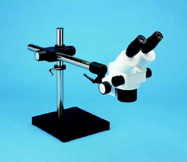
Stereo Microscope. Anyone who is doing serious SM work must have
a good stereo microscope for soldering, desoldering, inspection, or probing
operations. When selecting a microscope, be sure to pay particular attention
to the working distance -- the clearance between the microscope objective lens
and the item that it is focused on. I once worked with an otherwise fabulous
microscope that had only two inches of working distance. Boy, was it ever
easy to burn the plastic ring light on that microscope with a soldering iron!
A negative power lens will increase working distance more than it will
decrease the magnification.
Scienscope supplies reasonably priced
stereo microscopes.
Good tweezers. Tweezers are next on my list since they are the tool
that you will handle most. I prefer foam cushioned stainless steel tweezers
with curved tips like the
Erem 7SA. A good pair of tweezers will make your life much easier!
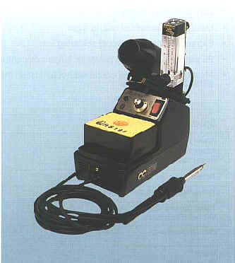
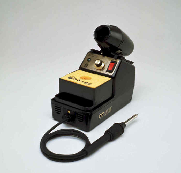
Hot air soldering iron. A hot air soldering iron is useful both for
initial soldering and for desoldering. My choice of hot air tools is the
Edsyn 971HA. It is one of the less expensive
units but is still quite capable. In fact, it has some features (possibly unintended)
that make it easier to use than most hot air soldering tools. The most important
of these is that the air tubing from the base to the handpiece is flexible and
runs at a position where you can squeeze off the air flow with your index finger
while moving the iron near to the component that you wish to work on. This
prevents blowing off dozens of components while getting everything arranged
under the microscope! This soldering station is intended for operation with
compressed air and it comes with air handling hookups. I don't have shop air,
but rather than pay hundreds of dollars more for a unit with a built in pump I
went to WalMart and bought the largest aquarium air pump they had in stock. With
very simple and reversible modifications, the soldering iron works quite nicely
with this air source.
I recommend Howard Electronics as a source
for microscopes and soldering supplies.
Stainless steel shim pin lifter. The quickest and least damage-prone
method of unsoldering large surface mount integrated circuits is to use a stainless
steel shim in an exacto-knife handle. Carefully slide the shim under the pins of
the IC while heating with the hot air soldering iron, and they pop right off.
I have desoldered many .5mm pitch QFP parts using this technique, and have been
able to reuse the parts and have not damaged any of the pads on the board. This
method is also quite rapid. A 48 pin part might be removed in as little as 30
seconds. And it doesn't require expensive, complicated special purpose hot air
nozzles. This technique is championed by Edsyn, who include a roll of stainless
shim stock with their soldering irons. I've not seen this method described anywhere
else.
Fine tipped soldering iron. I use a contact (traditional) soldering
iron for most initial board building. A well-tinned very narrow tip is a must.
Any manufacturer's iron will do but the smaller and lighter hand pieces are very
nice for big jobs.
You might try the Edsyn 951SX:
Flux pin. After swapping many components to find the correct values,
it's inevitable that the solder on the board will become grainy and laced with
impurities. I like to use a
Kester low-solids flux pin to clean the board
up and make better solder joints. With one of these pins you simply touch the
contaminated solder and gently reheat the area with the hot air soldering iron
(being careful not to blow parts away), and the solder gets bright and shiny as
if by magic. Better still, with a low-solids pin, you don't even have to wash
the flux off afterwards.
Several years ago, many of the no-clean fluxes were useful only for digital circuits
since they had relatively high conductivity and would interfere with the operation
of any high impedence analog circuits. With the new low-solids, no-clean fluxes
that are out now, I have not run across this problem.
In conclusion, I have found that the proper tools make prototyping with surface
mount components easier and faster than any of the traditional prototype methods.
Certainly it is no longer an onerous task to be avoided at any cost!
An Overview of the Universal
Serial Bus (USB) (Part II)
-- by Danny Simpson,
Pegasus Technologies
The USB Seal
Introduction
In Part I, we reviewed the history of USB, going over some of the communication advantages of
USB over RS-232, and then touching on the various USB data transfer protocols. USB is a somewhat
complex communications protocol but like many things, if you take it one step at a time, it can
be digested. In this issue, we will recap some of the basics as well as get into more of the
details involving the Windows drivers and their requirements. Also, we will go over some of
the capabilities, shortcomings, and limitations of USB. Again, we are covering here the USB
1.x spec dealing with the low speed 1.5Mbps and high speed 12Mbps transfer rates. USB 2.0
devices (480Mbps rates) are not expected to have support from Windows until late 2001.
USB came into existence because of the need for interfacing a number of relatively fast
peripherals to host systems such as a personal computers. Many peripherals must be installed
inside the computer. In the past, just about the only way to add a new device to a computer
was to turn off the power, remove the cover from the computer, find an empty PCI or ISA slot
in which to install a 'printed circuit card', install the new card, replace the computer
cover, turn the power back on, get the computer to install the driver(s) for the card, and
hope that the computer system still works properly after your efforts. Many of today's
computer systems only have 2 or 3 'spare' slots for new PC cards which can be a big limitation
for some folks. Also, with PCI bus, there are limitations where some PC card slots share
interrupts, and some card slots cannot be used with a PCI bus mastering card installed in
them. As many PCI cards these days do have bus mastering built into them, these cards often
will not work in those particular card slots. Theoretically, with USB you can install up
to 127 different devices per USB port. Most PCs have 2 USB ports yielding up to 254
devices connected to a single PC! In reality, it can get a little sloppy on your desktop
with this many USB devices, cables, and the hubs taking up room. Also, if you try this
route you are probably going to run up against USB bandwidth limitations...
You cannot connect two computers directly together for communications purposes using a
USB connection. However, you can hook two computers together using a peripheral called
a USB bridge, also known as a USB to USB adapter. USB is not intended to be used like
a LAN, so if you need to connect up two or more PCs together, you need to use Ethernet
or something equivalent. If you need to connect USB devices to a host farther away
than the maximum cable length of 3 meters for low speed (1.5Mbps) USB or 5 meters for
high speed (12Mbps) USB, you will need to use hubs to extend the connection distance
up to a maximum of 25 meters (5 hubs maximum, with 5meter cables between each hub).
When a device is added to a USB port, Windows on the PC side recognizes the connection
and adds the proper previously installed driver to support the device. Many hardware
devices that are plugged into the PC's USB port need to have a specialized driver
written to support the device. Also, in some cases, specialized software applications
will need to be supplied with the device to make it functional on the PC.
USB Driver Development
There are at least a couple of ways to get drivers that Windows can use for communications
with a USB device: you can 'roll your own,'or you can make use of a set of USB drivers
that the newer versions of Windows have included either on the Windows CD or that are
available from resources such as those included in the Win DDK. Device descriptors
inside each USB device contain information that Windows needs to know about the device
before it can be used. Descriptors for a minimal device are mentioned below.
Windows Supplied Drivers
There is a set of drivers included in the newer versions of Windows that support certain
devices called 'human interface devices' or HIDs. These devices include keyboards, mice,
game controls, remote controls, and joysticks. In general, these devices don't require
a great deal of data to be transferred to or from the host computer. The firmware inside
these peripheral devices must support the Windows HID protocol if you want to use the
existing HID drivers. The data that is transferred to and from these devices to the
computer are called reports. Using HID, transactions can contain up to 64 bytes of
data per transfer in high speed mode and 8 bytes of data in low speed mode using the
HID drivers. Maximum speed of data transfer is also limited. A high speed device can
only transfer 64K bytes per millisecond and a low speed device can only transfer 800
bytes per 10 milliseconds. Also, HID uses the control and interrupt pipes for data
transfers (see our first article on USB for a
discussion of this topic) which the USB protocol defines. As a result, HIDdoes not
guarantee timely data transfer. If you need data to be delivered at a certain critical
time, HID is probably not the way to go. As usual, the computer is the host and
initiates all transfers. Even with these limitations, if you only require low volume
data transfers, you can save a bit of time by using the Window HID-supplied drivers
instead of writing your own software drivers.
A fairly rigid protocol must be adhered to when using the HID drivers with your device.
Windows needs to determine which driver to load into memory to support a particular
device that has been inserted into the USB port. It does this by issuing what is
called a Get_Descriptor command to the device. What is returned to the PC host
from the device is a block of information that tells the PC certain facts regarding
its operation such as what class the device is, the number of logical interfaces
it has, the size of its endpoints (data buffers), the vendor ID, product ID, and
possibly serial number information. It is the class information that determines
whether Windows can use its existing HID drivers.
After the Windows device drivers have been installed and the devices are connected
to the host's USB port, Windows uses the Windows Device Manager to determine which
USB driver to use with which device. It makes this decision based on a user-supplied
.INF file that contains information such as manufacturer and product data, if the
device is a non-HID device. If it is a HID device, it will use the .INF file named
hiddev.inf for information on the device. This file also contains information that
will be added to the registry once the device has initially been installed in
Windows. Windows then uses data from all the .INF files (located in the \Windows\INF
directory which is normally hidden) to catalog the data into two files named
drvdata.bin and drvidx.bin for quick access to the proper .INF files
to retrieve data for a particular device. If you do change the data inside an .INF
file, you must go through a specific procedure to get Windows to change the entry
for the device in the registry by using the Device Manager or else the changes
will not be made when you expected them to. An .INF file has a format similar
to the familiar .INI file.
User Supplied Drivers
If you cannot live with the limitations that the Windows HID driver imposes on you,
you will need to write your own Windows drivers to communicate with your USB device.
This can get quite involved and you may need to have access to several additional tools.
As discussed in the previous article, you will need to determine your devices' data
transfer requirements -- such as which data transfer formats that you require for
its use. You can have one or more of these data transfer formats identified in your
device. Control mode is needed as a minimum for all USB devices for the query and
setup of your device with Windows. If any of the following modes are required,
Control mode also needs to be included. If data accuracy is important, you will need to
use bulk mode, but you will need to give up guaranteed timing of data delivery as
USB tends to give bulk mode its lowest priority. Bulk mode transfer is only available
in high speed mode and includes error checking. If guaranteed timing of data delivery
is more important than data accuracy, then you need to use isochronous mode of transfer.
Isochronous mode transfer is also only available in high speed mode. You need to sacrifice
one primary need for the other in these cases, i.e., transfer rate verses accuracy.
If you need to be 'serviced' from the host at irregular intervals, you can use
interrupt mode where the host will query you at regular intervals to see if you
have an 'interrupt' pending to the host. You cannot interrupt a host in the usual
sense, as it needs to ask you if you have anything pending. The host initiates
almost all transfers except for remote wakeup.
Windows drivers typically 'isolate' applications from the details of the physical and
logical aspects of the data transfer protocols. Much of the handshaking used is not
seen by the application program, and neither is the structure of the packets and error
checking. Drivers are seen as 'layered' between the hardware and the application
program. You can use existing Windows drivers and write a mini-driver which adds
to the capabilities of the existing driver. There is also a generic driver that
is available called bulkusb.sys that can be used as a starting point for performing
bulk mode transfers. Windows allows drivers greater privilege than applications
programs by letting them have unrestricted access to system resources using IRPs
(I/O request packets) to communicate with the lower level Windows USB drivers.
Applications, which use the Win API to communicate with Windows, run in user mode
while the drivers can run in kernel mode.
Communication Modes
There is a strict structure when using USB as a communications medium. After a
device has been detected by the host, its device descriptors have been read,
and it has been enumerated and assigned a handle by Windows, then an adherence
to the set mode of communication mode must be kept. The control mode is the
initial point of contact between the host and the connected device. Control
mode in addition may be used for very limited user data volume between the
host and the device. It is here where the host determines the device's setup
such as communications modes, IDs, and general configuration. Control mode is
the most complex mode of the four communication modes and has quite a bit of
overhead on top the actual data transfers. There are many packets of data
initiated by the host in this mode to the device and also packets of data
are sent back by the device in response to the host. There are also several
stages of communication such as Setup, Data, and Status stages, all which
are structured. There are a total of eleven different USB standard requests
in control mode where the host can set or get various parameters from the
device. The USB standard also allows vendors to define their own additional
requests in addition to the eleven provided.
The other three communication modes are generally used for user data transfer
between the host and the host's connected devices. The basic 'gives' and 'takes'
between these different modes has already been discussed above. Obviously, if
you are using a custom Windows driver to communicate with a device, the device's
firmware must be written to support the communication modes of the driver. It
is imperative that good documentation be kept to document the different
communication modes or the software and firmware development could get pretty
'outta whack' especially when working in a larger team project. The USB bus
drivers that come with Windows are based on the WDM (Win32) drivers, and
drivers written for your device should also be written based on the same WDM
model. Remember, there are 'layers' of these drivers communicating with each
other as well as the 'top' layer driver communicating with the application
and the 'bottom' layer driver communicating with the USB hardware itself. Each
driver has a limited set of tasks that it performs in conjunction with other
drivers that also have assigned tasks.
Also remember that hubs need to be involved in the communication chain. They
also have their internal firmware 'smarts' to make various decisions such as
when to disconnect a downstream device that is not behaving properly. There
is a hub driver within Windows that is used in the above-mentioned 'layers'
that does the direct communication with the downstream hubs and also handles
the enumeration. The USB bus-class driver assumes the responsibility of hub
driver and the host-controller driver. It is this host-controller driver
that does the direct communication with the hardware. You can see how the
different tasks that are defined in the USB protocol are assigned the
different tasks. When an application closes or no longer needs a USB device,
it closes the device's Windows assigned handle to free up limited system
resources -- which is imperative in Windows applications.
Tools
There are some software tools available from the USB.org Developer's section
of the USB Implementer's Forum to help verify your software. USBComp.exe,
available from http://www.usb.org/developers/tools.html [Editor's note 2/1/09: this utility is still available from
http://wareseeker.com/free-usbcom/], contains a series
of several test programs that allow you to check out your device to see
how it functions when connected to USB, whether you're using HID or your
own Windows driver. This at present is only for computers running under
Windows 2000. In particular, have a look at USBCheck which is included in
USBComp.exe. There also are several USB protocol analyzers available which
will allow you to see all traffic on the USB port. Using one of these is
probably the best way to assist you in the development stages as well as
thoroughly checking the operation of your device. As always, you can
download the latest USB specs and current important documentation from
http://www.usb.org/developers/docs/.
We have covered quite a bit regarding the basics of USB in these two articles.
There are more details available at the USB Implementer's Forum web site that was
mentioned above. Also, the web has many other resources to help educate you
further on USB or provide USB development tools available for either lease or
purchase. Be sure to check out SSS Online's USB page
for more information and listings of some of these sites. At Pegasus / SSS-OnLine,
we strive to help you with all your communication needs!
FCC Considerations for Spread Spectrum Systems -- By Jim Pearce, Director,
Pegasus Technologies
Oftentimes, potential clients call me with a great idea for a spread spectrum system. It
fills a market need, it's feasible from a technical standpoint, and it's just plain sexy.
On further discussion, though, it becomes evident that the system as contemplated (or in
some cases, as already designed and ready to go into production) will not pass FCC
Part 15 certification. While FCC experimental rules will permit the initial design
and prototyping of many of these systems, any systems that are to be manufactured
for sale must be certified under FCC Rules.
47 CFR Part 15 deals with unlicensed RF devices. "Unintentional or intentional
radiators" (i.e., radios, computers, or other emittors) that are to be manufactured
for sale must either meet the requirements for this part, or must meet Part 2 requirements
and their operation must be licensed. Part 15 is aimed at ensuring that unlicensed operation
does not result in interference with other RF systems, and this means keeping transmitter
power low. For this reason, external, stand-alone amplifiers of any kind are not permitted
under Part 15. (You can download FCC's Part 15 rules directly from our
FCC Rules page, or you can go straight to the
FCC itself.)
Section 15.247 allows up to 1 watt of transmitter power for spread spectrum
systems that operate in the 900 MHz, 2.4GHz, and 5.8GHz unlicensed bands. One watt
is quite a bit of power, and this makes certification under this section an attractive
target for new products that need up to a mile of range. In order to be certified
under this section, however, a system must meet certain listed requirements, including
a specification for processing gain for direct sequence spread spectrum data links.
A key point here: Both the transmitter and the receiver must exhibit processing
gain to qualify as a spread spectrum system under section 15.247.
The FCC has issued several interpretations that touch on the necessity of a
receiver to exhibit processing gain. It should be noted that these interpretations
often do not have the original question included with them, just the FCC's response.
Because of this, you must try to piece together the original question from the text
of the FCC's answer quoted below (All added emphasis is my own):
This is to confirm our telecon of April 27 regarding the
wireless personal locating system described in the referenced fax. Based on the
information provided, it appears that your system fails to comply with the
requirements of Section 15.247 of our Rules. As explained in your fax, the
normal measurement process performed by your system consists of three basic steps:
Step 1: The system "RDF" units transmit a standard direct sequence signal
(with ASK-modulated enabling message) to the 'BT' units. It does not
appear that the 'BTs' correlate the received spread spectrum signal and,
therefore, they do not demonstrate processing gain as required by Section 15.247(e).
Since we view a spread spectrum system as a transmitter and the associated receiver
with which it is communicating, the 'BT' receivers must display the required processing gain.
Step 2: Operating under the provisions of Section 15.249, the desired 'BT'
shifts the frequency of the incoming 'RDF' signal and transmits it back to the 'RDFs'
with an ASK-modulated acknowledgement message. This is acceptable operation under 15.249.
Step 3: The 'RDFs' transmit a spread spectrum signal to the 'BTs' for 130 ms.
The 'RDF' receivers despread the signal returning from the desired 'BT' and determine
ranging information by calculating the time delay between the outgoing and returning
PN sequences in the spread spectrum signal. This aspect of system operation fails to
comply with the definition of a spread spectrum system contained in Part 2 of our Rules.
Under this definition, only 'a portion of the information being conveyed by the system
may be contained in the spreading function.' As described, all of the information
being conveyed in this step of the location process is contained in the spreading
function. Based on the above, your system is not acceptable for authorization under
Part 15 of our Rules.
The FCC seems pretty firm on this issue, and even though they are charged with
supporting innovation they do not use this mandate as a method to get around the
Section 15.247 requirements. They want systems to meet both the letter and the
spirit of the regulations, as discussed in the following interpretation:
This is in response to the referenced fax regarding
[petitioner's] gas and electric meter modules. You indicate that these transmitter
modules are currently authorized under Section 15.231, and inquire about
the possibility of approving them as spread spectrum devices under Section 15.247.
We have examined the technical information you provided to support your request,
and find that there is insufficient justification for authorizing the referenced
equipment under 15.247. Although the subject modules demonstrate frequency
agility by successively transmitting redundant meter data on a series of 8
frequencies, they fail to comply with the requirement of Section 15.247(a)(1)(i)
which mandates a minimum of 50 hopping channels. Additionally, the associated system
receivers do not comply with the synchronized hopping requirement of 15.247(a)(1).
In place of synchronized frequency shifting receivers, the ... system utilizes a
bank of 48 fixed-tuned receivers to cover the operating frequency band. In your
fax, you acknowledge that an individual module does not comply with the r
equirements of Section 15.247, but that when viewed as a system consisting of
thousands of devices, the "spirit" of the law is met. Unfortunately, our rules
do not provide latitude for approaching authorization of these modules from
this perspective.
From this it is evident that any system where the receiver does not exhibit
processing gain will have a difficult time overcoming the FCC part 15.247
certification hurdle. Another FCC interpretation that addresses this point is the following
discussion on spread spectrum repeaters:
An application for a repeater that consisted of a RX
front-end, down-converter, up-converter, amp and antenna (port),
retransmitting at spread spectrum power levels was denied.
While such devices may be authorized under licensed Rules Parts (formerly Type
Acceptance), they cannot be authorized under Part 15. As a part of a licensed
system, they would only receive signals licensed to operate on certain specific
frequencies. A Part 15 repeated such as this one, however, could receive, amplify
and retransmit ANY incoming signal (the [Xxx] device, operated in the 2.45 GHz
band, so it could, in theory, have received and retransmitted emissions from a
microwave oven).
We have authorized repeaters under Part 15 where they demodulated the incoming
signal in order to determine if it was 'valid', I.e., it came from a specific
device with which the repeater was designed to operate. In these cases, we
list the FCC ID of the transmitter with which the repeater operates on the Grant.
In the [XXX] case, the difference is that it does not demodulate the incoming signal
in order to identify its source. This cannot be allowed under Part 15. The actual
Rule Part for the denial was 15.247(e), which requires that a direct sequence
receiver realize at least 10 dB processing gain. The receiver portion of the [Xxx]
repeater realizes no Gp, as it does not correlate or demod. If the device had
been designed to operate with a hopper, Section 15.247(a)(1) would have been
cited, which requires that a frequency hopping receiver have an input bandwidth
matching the transmitter bandwidth, and have the ability to hop in sequence
with the transmitted signal.
We will only grant a spread spectrum repeater (or any Part 15 repeater) if it has
the ability to determine the source and validity of the incoming signal, and
only retransmits signals from a specific transmitter, which is listed on its grant.
I have had occasion to discuss this issue with an FCC representative in the
Office of Engineering and Technology. Without identifying the client or the actual
application, I explained the basic operation of a client's proposed system and
asked him to comment on it from a certification point of view.
The fellow said that there would be no problem certifying the system as long
as it demodulates the signal and then retransmits the digital stream. I asked
if operation without the demodulation would be certifiable. He confirmed that since
it would not exhibit processing gain it would not meet the requirements of 15.247(e)
and would not be certified.
If a system can't be certified under section 15.247, there are some other
options to consider. These include:
Designing the system so that both the transmitter and the receiver exhibit the required
processing gain;
Designing the system so that it will meet FCC part 15.249 (with its power
limitation of approximately 1 mW);
abandoning the 2.4 GHz band in favor of a band that allows more leeway for
innovative concepts, such as the 5 GHz NII bands;
Petitioning for an exception (although these are hardly ever granted); or
petitioning for a rule change - but don't hold your breath while waiting
for this to happen.
As you can see from the discussion above, it is very important to consider FCC
issues at the very start of a design project. These issues can have a very major impact
on the entire concept of the design, and early consideration is vital to avoid wasted time
and money designing a system that can't be certified for sale.