We are now soliciting ideas and articles for our thirteenth issue, which is tentatively scheduled
for late fall. Please send your comments and suggestions to:
What's New At Pegasus Technologies
and SSS Online
Pegasus Technologies and SSS Online on the Move
We're going to be moving! We started out with one room in our home, and have since grown to the
point where we have people working in 4 different locations within a twenty mile radius. This
is not ideal, and has made communications a continual challenge! So, about a year ago we started
looking for a permanent space where we could all work together. We have just signed a lease
agreement for a new building to be constructed on a 4.6 acre parcel in the Roane Regional
Industrial and Business Park, less than a mile away from I40 close to both Knoxville and Oak Ridge,
Tennessee. It's a very beautiful site, as you can see from the picture. We are
working with architects and builders to come up with a final building design, one that's expandable
so if we continue to grow as we have been, we won't have to move again. We hope to move in around
the end of the year, although that may be a bit optimistic.
The site for our new office
We Helped Record History!
Did you see the video of Spaceship One in its historic flight into space on June 21, 2004?
The pictures of the takeoff and landing taken at the runway were transmitted back to the
America by Air production center over a Pegasus Technologies wireless video link design!
It worked very well, as you can see in this
video clip.
Changes to Pegasus Tech's Module Lineup
This has been a really busy time since our last issue. We've got several new RF modules up on
our RF Module Sales page. Take a look at our new LOW POWER versions
of the PTSS2003, which offer ultra-cool operation and extreme battery life. These are available
in the 902-928 MHz band, at at 868 MHz. These two new modules use the Xemics XE1202 chip, and
have an onboard microcontroller. Most of our modules have FCC and Canadian certification, and
the 868 MHz version has been tested to the RTTE standard for use in the European market. Development
kits for these modules are also available. Improved production efficiencies and increased volume
have allowed us to lower our prices again! New modules are in development, including a 433 MHz
version of the PTSS2003 and a brand new 2.4 GHz module with onboard microcontroller.
You can purchase these modules and accessories through our online store, with secure checkout
available that accepts Visa and Mastercard. Of course, you can also go the phone-in route
and get your questions answered at the same time. We can customize these modules as well,
and offer full technical support for getting them incorporated into your application.
Spread Spectrum Scene Completes its 9th Year Online
We celebrated by finishing putting up all the old paper copies from the early days, back in
1992 and 1993. Take a look at our Past Issues Index and check
out all those great old paper classics!
We're always looking for great technical content for this site. If you have something you'd like
to have published, please let us know. We can't pay cash, but do trade advertising space
for articles and papers from time to time, and also provide continuing advertisement through
prominent biographies and links that stay with the article forever.
drop us a line at .
We're always happy to hear your comments on any aspect of our website!
Danny Simpson is a Contributing Editor of SSS Online, and a Senior Associate
of Pegasus Technologies, Inc., a
provider of electronic RF and advanced electronic design services and RF modules. A
natural engineer, Danny is always fascinated by finding out how things work, and
provides SSS Online with the benefits of his research.
Overview:
Communications and interconnectivity, so important to the human animal, is more achievable
today than at any time in history. With the full flowering of the electronic age, fast and
direct digital communications between computers, peripherals, and a variety of embedded
devices are vital.
During the past 20 years, digital communications have been growing at a staggering rate.
The first popular digital communications protocol, EIA RS-232, has served well for many
years and is still in widespread use. However, as higher volumes of data needed to be
transferred faster and more reliably, many other digital protocol methods have been developed.
The Universal Serial Bus (USB) has become one of the most widely used methods of digital
serial data transfer during the last 5 years. USB connectors are now installed on most new
PCs and many new peripheral devices intended to be attached to PCs.
Firewire is another digital protocol whose development began well before USB, but currently its use
has not been as widespread. Firewire is a low cost, high performance, digital serial
interconnect that can be used for many digital items, such as audio-visual devices,
consumer PCs and home networks, and today its popularity is growing. The purpose of this
article is to serve as an introduction to Firewire; it will not go into the many protocol
details. For a similar introduction to USB, see our earlier article,
An Overview of the Universal Serial Bus.
Many of the newer PCs now ship with both Firewire and USB serial interfaces installed. As
a general rule, USB can be designed and manufactured into products for less money, but
Firewire does have several advantages. Unlike USB, Firewire has no need for a server or
central point to perform transactions. Firewire is a peer-to-peer relationship as opposed
to USB, which uses a master/slave relationship. There are many ongoing and sometimes heated
discussions over which protocol is better. Both support hot 'plug-and-play,' where a device
can be plugged into its respective bus and then enumerated before being used. However, because
of the differences between the peer-to-peer and master/slave protocols, this is handled quite
differently. Each Firewire node is exposed to all data traffic on the bus. Unlike USB, the
Firewire bus is daisy-chained; there are no hubs to contend with. The current data bandwidth
(under the latest Firewire and USB specifications) is fairly equal with Firewire being slightly
ahead, but there are differing overhead data requirements.
Ongoing development should continue to raise both standards to higher levels.
Both Firewire and USB devices may obtain operating power from their respective buses within
their bus power limitations. The Firewire specification currently has higher power
availability limits. There are many differences between the two high-speed protocols
and each tends to serve differently for differing needs. Both serve well for peripheral
devices connected to computers, although USB is currently the more popular of the two
for such devices. Firewire seems to be more popular in the higher bandwidth devices
such as consumer and industrial higher-resolution video products. Unlike RS-232 where
you could simply transmit raw data, both Firewire and USB protocols are very stringent
on how they are to be used. The transmitted data is arranged into formatted packets
that contain many details along with the data that they may be carrying. Despite the
complexity of the protocols, however, they are literally invisible for the person
making use of an end product that utilizes either protocol.
Of interest, there is a mechanism called a 'device bay' that can use either Firewire
or USB for attaching high speed serial bus devices to PC desktop systems by means of a 'hot
docking' arrangement. Microsoft, Intel, and Compaq developed this specification.
Using this system, devices such as hard drives or CD ROM drives may be added to
a computer without powering down. The proper device drivers are then dynamically
loaded to support the newly installed drive device.
Firewire History:
Firewire development first began in 1986, and the initial specification was completed
in 1987. The standard was adopted in 1995 as IEEE-1394. Cable length is specified as
a maximum 4.5 meters with a characteristic 110 ohms impedance using differential mode.
Initially, there were problems with devices not working properly together on the
Firewire bus. Supplement IEEE-1394a has since been issued, adding new features and
better performance as well as fixing these initial problems. Another supplement,
IEEE-1394b, is currently being developed. It is primarily aimed at supporting even
higher speed data transfers (up to 3.2Gbs) and longer distances (up to 100 meters
with the use of CAT5 cable, but limited to 100Mbps). It will be backwards-compatible
with the two earlier Firewire specifications. Because of speed constraints, IEEE-1394b
will more than likely be available only in newer ICs that have the PYS (physical) and Link
layers combined. IEEE-1394 is based upon the IOS / IEC 13213 (ANSI / IEEE1212)
specification commonly referred to as 'Control and Status Registers (CSR) Architecture.'
It defines a set of basic features that can be used by a variety of buses.
Firewire is a registered trademark of Apple Computer Corporation. It is generally
considered to have been developed by Apple, although there have been reports that
it was the result of a developmental process between several companies. Before using
Firewire in their computers, Apple Computer made use of Small Computer System
Interface (SCSI) for their Mac computer hard drive interfacing. Eventually, both
as a cost-cutting exercise and as a way to share fewer common interfaces
between devices, Apple did away with SCSI serial and parallel interfaces on
their newer Macs and replaced them with Integrated Drive Electronics, USB,
and Firewire serial interfaces.
In addition to Apple, Sony began using a four-wire version of Firewire in their
iLink interface, which does not supply power for devices. Yamaha is now using
Firewire for their mLAN protocol for high-speed music transfers. Many other
manufacturers are now designing products to work with Firewire. Firewire's
first main entry was in video applications. A large percentage of the new
consumer-based video products that are being designed today, such as video
cameras and digital video recorders, are being designed to work with Firewire.
Firewire Below the Surface
Unless otherwise mentioned in this article, the transfer rate of 400Mbps (megabits per second)is
assumed for discussion. The Firewire bus currently allows a scalable performance
depending on bandwidth requirements such as 400 Mbps, 200 Mbps, and 100
Mbps, and has the following features:
Hot plug and play enumeration
Currently 400Mbps (six wires)/ 800Mbps (9 wires) Higher speeds currently being
developed are 1600Mbps and 3200Mbps
Both Asynchronous (time not guaranteed) and Isochronous (real time) transfers
Peer-to-peer communications
Low cost
Power supplied to the interface (6 and 9-wire interfaces)
Networking using standard networking protocols
Firewire devices can send data directly to each other without the intervention of
a host. Unlike USB, a host is not used at all, since Firewire makes use of
peer-to-peer communications. Firewire supports 'hot insertion' plug-and-play.
When a new device is inserted or removed from the Firewire bus, devices on the bus
are re-enumerated. Since it is a peer-to-peer relationship, arbitration must be
performed to determine who will get bus usage. Arbitration is the process
of gaining ownership of the bus for a period of time. There is a fairness
interval algorithm that helps determine which node will get the bus, so
that the bandwidth guarantees made for both asynchronous and isochronous
modes can be adhered to. It ensures that all nodes have their turn to use
the bus. There is also a detection mechanism to identify and report nodes
that may be 'stuck' in a loop. A monitoring mechanism on each Physical port
monitors incoming power.
Some pre-defined classifications of Firewire devices use 'unit architecture'
details such as identical data protocols, device internal register
implementation, and addressing. Some of the benefits of this 'design
specification' are better inter-operability between other similar
devices and simplification of the entailing software design.
Nodes and Addressing
There can be 1024 buses in a single Firewire implementation, and each serial
bus can support up to 64 nodes. Therefore, Firewire can support up to 64K nodes.
Since each of the 64K nodes has addressable memory space of 256 terabytes,
Firewire's total address space is a huge16 exabytes (64K nodes x 256 terabytes)
and is based on the 'big endian' memory-addressing convention. The Firewire
specification additionally includes both cable and backplane implementations
of Firewire.
Firewire addressing works as follows. Firewire uses a 64 bit-addressing scheme
for a total of 16 exabytes. The highest order of 10 bits defines one of 1024
target buses. The next order of 6 bits addresses the 64 nodes on that bus.
The remaining 48 bits define the 256 terabytes memory addressing set aside
for each node. This node address space is divided up into blocks by the
standard for special purposes, including the initial Control and Status
Registers (CSR) register space, each node's private memory space, and
initial units space.
As mentioned at the beginning of this article, Firewire nodes utilize the
CSR Architecture register implementation. This allows a common arrangement
to be set up which improves interoperability between different platforms,
facilitates moving between different bus types, and allows for more consistent
software implementation. Also, CSR defines various ways of handling different
types of system failure and error handling as well as automatic configuration.
CSR additionally defines a standard method for configuring a local configuration
ROM. This ROM is used to help locate the proper drivers for modules, nodes, or
units as well as to assist in identifying local properties as they are being
enumerated upon connection to the bus. The CSR Architecture also defines a
Message Broadcast protocol in which a node can send messages to multiple nodes
simultaneously over node address 63, which is reserved for this purpose. An
Interrupt Broadcast message mode is also defined.
Firewire Data Transfer Methods
Firewire supports both asynchronous and isochronous methods of data transfer. In
both cases, the bus bandwidth is based on 125us time intervals (8000 times/second)
called cycles. Both asynchronous and isochronous transfers can be intermixed within
these cycles.
Figure 1: Firewire Packet Diagram
Asynchronous transfers communicate to a single node based on a unique 64-bit address.
Asynchronous mode does not require a continuous usage of the bus, but does allow
fair usage of the bus over time. For asynchronous error checking, a Cyclic
Redundancy Check (CRC) is performed and if an error is determined to have
occurred, a transfer retry is attempted. Most asynchronous transfers require
acknowledgment back to the data initiator, including whether the data was
received correctly. The Firewire specification defines error codes that are
to be returned from the responder (the receiver of the data and command)
back to the requestor (the originator of the data and command). Asynchronous
packets consist of seven different packet formats:
Read request
Write request
Read response
Write response
Lock request
Lock response
No data
Lock is used as a way to make a request for bus resources from a manager node.
The requesting node guesses if a resource is available, sends a lock request
packet for the resource (for example, channel 10) and if the requester is
correct that the resource is available, that resource is locked so that no
other node can obtain it.
Isochronous transfers use a pre-defined 6-bit channel number to broadcast
to one or more nodes that have been assigned to a particular channel address.
This mode is for transfers that are required at constant intervals, such as
ongoing video transmissions. This mode carries a higher bus priority over
the asynchronous transfer mode. Isochronous transfers do not require
confirmation of data delivery. In this mode, the data sender is known
as the 'talker' and the receiver of the send data is referred to as
the 'listener'. Isochronous transfers require initial negotiations
with the 'isochronous resource manager' to obtain bandwidth that will
be needed for the continuing data transfer. Isochronous packets consist
of only one packet format:
Data block
Communications using both asynchronous and isochronous transfers are
performed using packets of data. Asynchronous data packets can contain
destination address, the source ID, type of transaction (read, write,
or lock), response code (from a previous request), the actual data, CRC,
acknowledge message, and acknowledge parity. Isochronous data packets
are simpler containing channel number, type of transaction (read, write,
or lock), the actual data, and CRC.
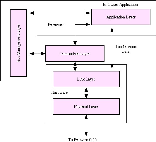
Firewire uses a software layering method for communications over its bus.
There are three layers used in isochronous mode and four layers used in
asynchronous mode. These three or four layers are used to communicate with what can
be considered a fifth, or Application layer, which is the actual program
or device that the user is working with.
Since the asynchronous mode requires more 'handshaking' than the isochronous
mode, an extra layer, called the Translation layer, is required to support this
protocol. The same three layers used in isochronous mode are utilized in
asynchronous mode along with this additional layer. These layers are:
Physical layer - The actual interface for transferring data between the
Firewire device and the Firewire bus. This layer provides the necessary
signal timing and mechanical interface. It is also used for bus configuration
when a device is either added or removed from the bus. During bus configuration,
each node is uniquely identified. This physical layer is generally implemented
with an IC such as Texas Instrument's TSB41LV03 or Philips PDI1394P23 along with
the necessary software. Newer ICs are available that contain both the Physical
and Link layers.
Link layer - Provides the 'assembly' and 'disassembly' of the packets
that are transferred over the bus. For outgoing packets, the encoding occurs
here. For incoming packets, decoding of addresses or channels occurs at this
level. CRC error checking occurs here for incoming data. For isochronous
transfers, the isochronous program/driver communicates directly with this
layer, bypassing the Transaction layer. This Link layer is generally
implemented with an IC such as Texas Instrument's TSB12LV22 or Philips
PDI1394L40 along with the necessary software. Newer ICs are available that
contain both the Physical and Link layers.
Transaction layer - Used exclusively for asynchronous data transfers.
This layer supports the CSR Architecture specification for the request-response
'handshaking' protocol.
Bus Management layer - Provides initial node configuration as well as
overall management of a node. This layer works in conjunction with other
nodes on the Firewire bus to form a 'global' management system when required.
This global system handles items such as defining isochronous channel numbers
and bandwidth, and handling available bus power and optimizing bus bandwidth
during packet transfer.
Each 'requestor' synchronous data transaction is followed by an acknowledgement
by the receiving 'responder' for each packet transferred. And in turn when the
'responder' handles the actual request back to the 'requestor', the original
'requestor' sends back an acknowledgement back to the 'responder'. The
previously mentioned Transaction layer handles these 'handshaking' functions.
Figure 2: Diagram of Firewire Layers
Negotiating for Bus Usage
When any node needs to perform a transaction over the bus, it must use arbitration
for bus usage. Firewire's design works to make data transactions as efficient as
possible. It can multiplex requests from multiple nodes and respond simultaneously
to each request. It also may use 'concatenated transactions' and 'unified
transactions' to help eliminate usage inefficiencies.
Concatenated transactions can eliminate the problem caused when a slow response
from a node causes it to lose its place in the bus line. For example, if one
node is waiting on a response from a slow-responding node, transactions
between other nodes can occur during this waiting period. Then, when the slow
node is ready to return the acknowledgement message, it might have to start
the bus arbitration process all over again, which can waste bandwidth. If a
node is relatively fast, it can actually return its acknowledgement response
with its data response concatenated afterwards to help eliminate the possibility
of losing its place on the bus and having to re-arbitrate for bus bandwidth.
A unified transaction occurs when a write transaction has the acknowledge
and response completion codes coming back from the 'responder' combined into
one simple packet. However, a read transaction cannot work as a unified
transaction, as the 'responder' must include the requested data, which
cannot be part of an acknowledgement packet, and the completion status as well.
A single device that connects to the Firewire bus is called a 'module'. A module
can have one or more 'nodes' in the module, which are logical connections. A node
may be further broken down into more logical 'units'. In other words, a 'module'
can contain multiple 'nodes', which in turn may contain additional 'units'. This
flexible hierarchy simplifies system design. An actual physical connection
is made through a module's (device's) 'port'. When a multi-ported node receives a
packet, it is synchronized to the device's local clock and retransmitted to its
other 'local' units.
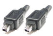
Hardware
There are several connector types that can be used when connecting to the Firewire
bus. The original 1394 specification mandated a 6-pin connector that can also carry power.
As with USB, when using the power capabilities of Firewire, the power pins are a bit
longer than the signal pins, giving a 'make first/break last' power connection as the
Firewire connector is being inserted and removed. The 1394a supplement added the option
of a smaller 4-pin connector, which does not have the capability of sourcing or
receiving power to Firewire devices. Sony makes use of this connector in their video
cameras. The cables in both cases have outer shields as well as shields on each of
the two twisted wire pairs.
The Firewire 1394/1394a 400Mbps data transfer is performed bi-directionally over
two twisted-wire pairs in a half-duplex manner. One wire pair is used for data
transfer and the other is used for synchronization. The Firewire 9-wire configuration
is to be used with the 800Mbs specification. If a 6 or 9-wire system is used, another
pair of wires carries power to or from Firewire devices. A Firewire device can either
be a power source for other devices connected to the bus, or it can receive its power
from the Firewire bus.
There are differing mechanisms in the different Firewire specifications that determine
when a device has been connected or removed from the Firewire bus. The Firewire
specification also gives much attention to items such as speed signaling to determine
data delivery rates as well as various types of control/status signaling. Both
differential and common mode signaling are used to generate various special internal
functions, much like interrupts occur in microprocessors. Firewire utilizes NRZ
encoding to help reduce the frequency component in the serial transmission. The
recovered clock is generated on the receive end and is obtained by data being
exclusive OR'd with the data strobe.
Firewire can supply voltage to power devices connected to the bus. This voltage
can range from 8 to 33VDC at a maximum of 1.5amps. There is a detailed power
state management section in the Firewire specification that specifies how control
can be managed for the power states within nodes, or even within units inside
nodes. There are a total of four power-on states that can control the power within
each node as well as four additional power states that control the power of individual
units within that node. Nodes that are in a low power state can be notified to wake up.
A Node can alert the power state manager of its current power state. One node can control
another node's power functionality.
Engineering notes:
There are a number of developmental resources on the Internet to assist in the
development of a product that is being designed to operate on the Firewire bus.
Most of the manufacturers who produce ICs for use with Firewire have many reference
designs available. Some of our favorite links are listed in the box below.
We were recently commissioned to redesign a remote control transceiver operating in the
902-928 MHz license-free US band. The client had an operable unit, but its output
spectrum was so ugly that the possibility of passing FCC certification testing was nil.
The original board had been layed out by a competent PCB engineer but he was not
knowledgeable about RF layout issues. There was little in the way of ground planes,
no via grids to connect a top and bottom ground pours to the inner ground plane, no
controlled impedance traces, etc.
We addressed these and other problems by re-laying the board, taking good RF performance
into account. Soon we had the revised board in our hands, populated and ready to check out.
The firmware in one of the boards was set to make the board continuously transmit at a
frequency in the middle of the band. This allowed us to easily verify the spectral
purity and power of the RF output signal. By replacing the normally soldered monopole
antenna with a short section of micro co-ax (I like to use Digikey part number 229-1007
along with an SMA adapter) we were able to measure the output power into 50 ohms by
simply connecting the co-ax to the input of a spectrum analyzer.
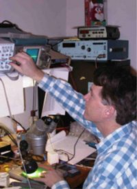
This is where the fun started! The power was low --- way too low. The transmitter
had been designed for an output power of about +20 dBm or 100 mW but we were only
seeing about +6 dBm or 4 mW. So where does one start to see why the power output
is so low in a situation like this?
The first thing we noted was the power supply current. It was what we would expect
for full power operation, so we were convinced that the power was being generated -
it was just not making its way to the antenna connection.
Debugging a board in the lab
Next we isolated the RF output stage-by-stage. We connected more of the micro co-ax
to various spots in the output chain, starting with the output of the RF integrated
circuit. We were careful to break the connection to the next stage by removing a
coupling component, such as a coupling capacitor. We were also careful to be sure
that there wasn't a DC path to ground on our output tap. We would then fire up the
transmitter with our tap connected to the input of the spectrum analyzer and measure
the output power.
This particular transceiver consisted of an RF integrated circuit, SAW filter, RF
power amplifier, transmit / receive switch, and a discrete component L-C low-pass
filter. We moved the micro co-ax tap to the output of each of these stages to
check the output power levels. Everything looked fine; even the output of the
T/R switch was well over +20 dBm. This focused our attention on the L-C filter
since the power was fine ahead of it but lousy after it.
We placed micro co-ax on the input and output sides of the L-C filter so that we
could measure its frequency response and insertion loss. We used a sweeped frequency
signal generator for this test, since our spectrum analyzer with the internal tracking
generator was in use on a different project.
This rapidly showed that the filter, which was supposed to have a 950 MHz 3dB cut-off,
had a 600 MHz cut-off instead! We changed the values of a couple of inductors and one
capacitor and we got the sort of low-pass response that we were expecting.
We removed all of the micro-coax (except for the output connection), replaced the
coupling capacitors, and turned the transmitter on. The output was now just what
it should have been and the spectrum looked nice and clean.
The time from first power to good output power was only a couple of hours.
FCC Modifies Rules for Unlicensed Devices by Karen Edwards, Pegasus Technologies
On July 12, 2004, the FCC issued a Report and Order
(R&O) modifying Parts 2 and 15 of its rules for unlicensed devices and equipment approval.
The Notice of Proposed Rulemaking was released September 17, 2003. By this modification, the
FCC adds flexibility that it hopes will encourage continued innovation in broadband technology and services.
Since unlicensed devices form the bread and butter of Pegasus Technologies' work, we have been
following this rulemaking very closely. We reported on the proposal in our
October 2003 issue and provided comments to the FCC. We
didn't get everything we wanted, but we were one of the commenters named several times in the R&O,
so we know for sure that our comments were considered — and that's gratifying!
The revised rules will:
Permit the use of advanced antenna technologies ("smart antennas") with 2.4 GHz
spread spectrum devices (updated Section 15.247);
Modify the replacement antenna restriction for Part 15 unlicensed devices;
Allow RF transmitters to be marketed separately outside of transmission systems,
as long as each complete system that the transmitter can be used with has been tested;
Permit digital modulation systems authorized pursuant to Section 15.247 of the rules
to use the average measurement of output power like U-NII devices authorized under
Sections 15.401 - 15.407; and
Modify the channel spacing requirements for frequency hopping spread spectrum devices
in the 2.4 GHz band in order to remove barriers to the introduction of new technology
that uses wider bandwidths.
A brief summary of each of the proposed changes, the comments, and the final rules are summarized below.
Advanced Antenna Technologies
Previously, the rules provided only for use of omnidirectional and point-to-point antennas,
and set limits on the amount of directional gain that may be used by each type.
The proposal would have permitted sectorized or phased array antenna systems that must be
capable of forming at least two discrete beams with a total simultaneous bandwidth not greater
than 120 degrees, regardless of the number of beams formed. In addition, the proposed rules
would allow these types of antennas to operate within the higher limits currently allowed for
point-to-point antennas, with an upper limit that the aggregate power transmitted simultaneously
on all beams could not exceed 8 dB above the limit for an individual beams. Finally, the FCC
proposed that the transmitter output power must be reduced by 1 dB for each 3 dB that the
directional antenna gain of the complete system exceeds 6 dBi.
Commenters were generally favorable on this proposal (although we were not, fearing that
low-power applications in the 2.4 GHz band might be affected by the proliferation of relatively
high-power Wireless Internet Service Provider (WISP) signals that are likely to result from this
change). There was concern that the rules be flexible enough to allow different technologies
other than the ones specifically mentioned. Opinions were mixed on the various limitations in
the proposed rules.
Based on the comments, FCC's final rules will permit advanced antenna systems, including
sectorized and adaptive array systems, to operate with an aggregate transmit output power up to
8 dB above the limit for an individual beam. However, the total EIRP on any beam may not exceed
the EIRP limits for conventional point-to-point operation. The 120 degree restriction has been
dropped in favor of the new EIRP limits. Existing advanced antenna systems that have already
received an equipment authorization are grandfathered.
Replacement Antenna Restrictions
Before this new rulemaking, Part 15 required that intentional radiators be designed in such
a way that no antenna other than the one supplied can be used with the device. To this end,
the use of standard antenna jacks or electrical connectors is prohibited. This was an attempt
to ensure that the Part 15 emission limits aren't intentionally (or unintentionally) circumvented
by replacing the supplied antenna with another one with higher gain.
FCC's proposal was to modify this requirement to require testing with the highest gain
antenna of each type that would be used at maximum transmitter output power. Any antenna
of a similar type that doesn't exceed the antenna gain of the tested antenna(s) could be
used on that transmitter without retesting and approval. The prohibition on standard
antenna jacks would remain.
Comments were generally favorable on this proposal (including ours). However, several
commenters suggested that both in-band and out-of-band emissions must be considered in
determining if an alternate antenna is acceptable. Others argued in favor of eliminating
the restriction on standard antenna connectors, saying it was not working as intended
and added additional design complexity and unwarranted costs.
FCC has decided to permit the use of a variety of replacement antennas. Revised
Section 15.204 will allow multiple antennas of "similar in and out-of-band
gain and radiation pattern." Compliance testing for the intentional radiator
must be performed using the highest gain antenna that will be used with the device.
The manufacturer must supply a list of other acceptable antennas in the product
literature. FCC is retaining the requirement for non-standard connectors,
fearing that uninformed consumers might accidentally use antennas that would exceed
limits, if this rule were eliminated. However, it is removing the Section 15.407(d)
requirement that devices operating in the U-NII band must have an integrated antenna.
This is in recognition that equipment is increasingly able to operate across multiple
unlicensed bands, making it impractical to maintain separate antenna requirements for
each band in which a device may operate.
Flexible Transmission System Configuration
As the previous rules required equipment authorization for every combination of a
transmission system, it was difficult to mix and match components without extensive
retesting. This had an impact on WISPs and limited their ability to design systems
that meet the needs of the particular application without the additional time and
expense of retesting.
The Commission proposed several changes to the rules to address this problem:
(1) changes to permit limited marketing of RF power amplifiers outside of a specific
transmission system; (2) provisions that would permit "professional radio systems
installers" to configure systems using technically equivalent components without
requiring retesting of the specific system selected. This would, of course, put a
much greater burden on the technical competency of the systems installers to ensure
that their systems meet FCC regulations, but would enable both quicker deployment
and lower costs for WISP services.
Commenters, including us, were very concerned that the proposed rules went too far
in permitting the use of external RF power amplifiers without testing in WISP systems.
There was general agreement that this proposal, if adopted, would open Pandora's box
of escalating interference and violation of FCC rules. The Commission considered the
comments and modified its proposal. The final rules will allow external RF amplifiers
to be marketed separately, but only if they are designed in such a way that they can
only be used with a specific system (or systems) that is covered by an equipment
authorization, so that the complete system will still be ensured of compliance. Other
limitations on output power, and certain notice requirements, are also included in the
final rules. Because of these changes, there is no longer a need to define and provide
special authorization for "professional radio systems installers," and this
part of the proposal was dropped in the final rules.
Measurement Procedures for Digital Modulation Systems
Devices that operate under the Section 15.247 and those that operate under the U-NII
rules (Subpart E) are both limited to a maximum power output of 1 watt. However,
output power was measured differently for the two types of devices under the previous
rules. FCC proposed changes that would make measurements the same for both types of
devices - and would use the average measurement of output power (U-NII) rather than
the peak emission method previously used for spread spectrum devices.
Most commenters, including us, were in favor of this proposal. There were some concerns
that in certain cases the peak emission method would be better. So, in the final rules,
the Commission is permitting the part 15.247 devices to choose whether to use the average
measurement of output power or the peak emission method. If the average power
procedure is used, then out-of-band emission must be reduced to 30 dB below the level of
the device's fundamental frequency. Additional clarifying changes are being made to the
definitions of transmit power.
In its proposal, the FCC had solicited comments on whether it should amend the spectrum
occupancy rules for Section 15.247 and U-NII devices to apply the same limits to both
types of devices. There weren't many responses, and they were conflicting, so the
Commission has decided to leave the spectrum occupancy limits unchanged for the time being.
Frequency Hopping Channel Spacing Requirements
The previous rules for the 2.4 GHz band required a separation of 25 KHz or the 20 dB
bandwidth of the hopping channel, whichever is greater. The Bluetooth SIG suggested
a modification of the channel separation requirements for FHSS systems, to 25 KHz or
2/3 of the 20 dB bandwidth, whichever is greater. This would permit Bluetooth devices
to be capable of data rates of up to 3 Mbps. The FCC proposed to adopt this suggestion
for 2.4 GHz systems with an output power limit of no more than 125 mW and fewer than
75 hopping channels.
Commenters were strongly in favor of this proposal, however, most recommended dropping
the proposed limit of 75 hopping channels. We also proposed extending this modification
to the 915 MHz band. The Commission's final rules will modify the spacing requirement
for systems that are limited to an output power of 125 mW using any number of hopping
channels. They are not extending this provision to the 915 MHz band, because of the
differences in width of the band and insufficient information on the affects that
modifying the spacing requirements might have on existing users of the band.
Modular Transmitter Approvals
FCC had proposed to clarify the equipment authorization requirements for modular
transmitters. We thought that was a great idea, but it has been scrapped for the
time being. The Commission recognizes that there are many complex and evolving
issues associated with this subject at the present time, and believes it would be
better to wait and collect more information before proposing changed guidelines.
Spectrum Sharing
The FCC asked for comments on how spectrum sharing in the unlicensed bands can be
improved, and specifically whether the spectrum etiquette provisions that apply to
unlicensed PCS devices should be expanded to cover other types of unlicensed devices.
Most commenters, including us, were not in favor of spectrum etiquette provisions.
However, Microsoft recommended some spectrum sharing protocols that would require
devices to cease transmission if no information was being sent, allow unlicensed
devices to transmit only if they can do so without causing interference to other
devices already using the channel, and to require unlicensed devices to incorporate
dynamic range control which would force it to use the minimum transmit power
necessary to complete a communication link.
The Commission has decided not to impose any type of spectrum etiquette for the
already heavily-used Part 15 bands. However, they are considering the Microsoft
recommendations for any additional spectrum that may be made available for unlicensed
operation in the future. This would be the subject of further rulemaking, so be alert!
Special Temporary Authority
The FCC has decided to eliminate the STA provisions in Section 15.7. No one has
requested a STA in the last 10 years. Part 5 provisions for experimental licenses
are being used instead and seem to be adequate.
Conclusion
There's a lot more in the R&O that is not summarized here, including some
information on Part 2 changes, which aren't that numerous, and the actual language
of the changed rules themselves. We urge you to review the R&O carefully. Note
that the changes will not be effective until 30 days after publication of the new
rules in the Federal Register, and that may take a while - so we're not quite there yet!
FCC complete Docket file: go to
the FCC's Electronic Comments Filing System, and enter "03-201" in box 1,
Proceeding. Then press the Retrieve Document List button at the bottom of the
screen. This will bring up a list of documents that have been filed, and .txt files of all
comments and FCC documents on this topic. Interesting reading!
Over a year has passed, and there's no end in sight to the battle that still rages over which of
the two leading Ultra Wideband approaches will be selected as the standard. The two candidates
are the Multi-Band OFDM approach, which is supported by the Multi-Band OFDM Alliance (MBOA)
consisting of Intel and a host of other companies, and the Direct Sequence approach sponsored by
Freescale Semiconductor (a Motorola spinoff) and others. In the most recent meeting of the IEEE
committee tasked with developing a UWB standard, the Direct Sequence approach narrowly won an initial
vote but did not have the 75% necessary for adoption. In several previous meetings, the multi-band
approach won, but again, not by enough margin. Both groups are continuing to develop products
based on their own approaches, so this may have to be decided in the marketplace.
Keep on top of the latest in this battle by referring often to our UWB News page.
We have an automated news feed on this page, and also post information and links whenever anything new
and exciting happens in this area. You can see more details about the recent votes there, plus find
some great background information on the various approaches, the key players, and more.
Recognized as a career expert, Linda Matias brings a wealth of experience to the
career services field. She has been sought out for her knowledge of the employment market,
outplacement, job search strategies, interview preparation, and resume writing, quoted
a number of times in The Wall Street Journal, New York Newsday, Newsweek, and HR-esource.com.
She is President of CareerStrides and the National Resume Writers' Association. Visit her
website at www.careerstrides.com or email her at
linda@careerstrides.com..
It is rumored that the only word William Shakespeare wrote on his resume was "Available."
We'll probably never know if that is true. But it raises an interesting question. How much
information is too much and how much is too little when dealing with resume copy?
The resume is a vital piece to any job search. As companies scramble to find the ideal
candidate, they use the resume to screen candidates. Done right, a resume builds an
instant connection with the reader and helps steer the course of the interview in
your favor. If you submit a resume that piques the curiosity of the reader, he or
she most likely will ask questions based on the information you provided on the
resume as opposed to relying on a pre-packaged questionnaire. That's how you know
you have an "interviewable" resume, when it assists in shaping the course
of the interview.
The challenge is, How does one create an "interviewable" resume, one that
isn't boring or sterile? How does one write a resume that motivates the reader to give
you a call?
Write with the employer in mind
Cast aside the belief that the resume is about you - because it isn't. Though the
resume is your "story", the heart of it should focus on the needs of the
employer. When developing your resume give thought to the person who will be reading
it. What are his or her immediate concerns? How will you be able to solve that
person's problems?
Though it may be difficult to pin down a company's immediate concerns before an
interview, the reality is that organizations recruit candidates for one of the
following reasons: they need to replace an unproductive employee, a peak performer
was promoted or left, or a new position has been created. A recruiter usually
searches for a candidate who will produce certain results, one that is a skilled
communicator and has a strong work ethic. If you are able to target your resume
toward these key areas, you will, without a doubt, tap into the organization's concerns.
Choose your phrases carefully
Sentence starters and appropriate use of action words all determine whether the
resume is "interviewable." Instead of using predictable phrases, think
of ways to add punch to your resume. For example, instead of using increased
sales by 250% ... write delivered a 250% increase in sales...; instead of
using ability to effectively ... write demonstrated ability to effectively ... ;
and instead of using reduced costs ... write slashed costs.
When your resume doesn't "sound" like all the others on the recruiter's
desk, he or she will take notice. You will be remembered when your resume breaks
the monotony of the recruiter's day. Guaranteed.
Have a consistent message
Don't try to become all things to all people. If you are a CEO, don't add a statement
that indicates that you are willing to be a Business Manager. If you are a Sales Manager,
don't indicate that you are willing to take on a position as a Customer Service
Representative. Get the picture? Determine what you are selling (and looking for)
before you put one word to paper.
Determine your major selling points
Though you may share the same job title with many other people, your accomplishments
and how you carry out your responsibilities are what distinguishes you from all the
other qualified candidates. Focus your resume on not only what you did but also how
well you did it. By design, what makes you "interviewable" is how you
market your strengths on paper.