We are now soliciting ideas and articles for our eleventh issue, which is tentatively scheduled
for mid-fall. Please send your comments and suggestions to:
What's New At Pegasus Technologies
We are pleased to announce that, as of August 14, 2002, Pegasus Technologies is now Pegasus Technologies, Inc.
Formerly, we were a division of Pegasus Consulting Corporation, but as we have continued to grow, it seemed
more appropriate that we "spin off" into our own company. Pegasus Consulting Corporation will
continue to provide webmastering services for both Pegasus Technologies and for SSS Online, the entity that
owns this website.
What will this change mean to our clients? Not a lot initially -- Pegasus Technologies will still
provide RF design consulting services for our clients, specializing in design and development of RF links
for a wide variety of applications. We do plan to begin selling RF modules soon, using the outstanding
new Xemics XE1202 RF transceiver chip. Look for an announcement on this in the near future!
Bruce Bullard is a Senior Test Engineer in the SiGe
BiCMOS group at Atmel Corporation. He has a Bachlors
Degree and a Masters Degree in Electrical Engineering
from the University of Colorado in Colorado Springs
Atmel Corporation, founded in 1984, is a worldwide
leader in the design, manufacturing and marketing of advanced semiconductors,
including advanced logic, nonvolatile memory, mixed signal and RF integrated circuits.
Atmel is one of the elite few companies capable of integrating dense nonvolatile memory,
logic and analog functions on a single chip. Atmel chips are manufactured using the most
advanced wafer processes, including BiCMOS, CMOS and Silicon Germanium (SiGe) technologies.
Philip H. Smith developed the Smith Chart1 between 1932 and 1937. In the years past
a few changes have been made to the format. Microwave Engineers now have many CAD
tools for analyzing RF & Microwave circuits. These tools can generate input impedance
and reflection coefficients, and plot the data in many forms. The Smith Chart has
remained an excellent data presentation format.
The attached file is an Excel Workbook, which takes reflection coefficient data
in the real and imaginary format and plots it on a Smith Chart. The user can generate
the data using any method including using measured data from a network analyzer.
Numerous traces can be plotted, and the lines of constant reflection, resistance, and
reactance are adjustable by the user.
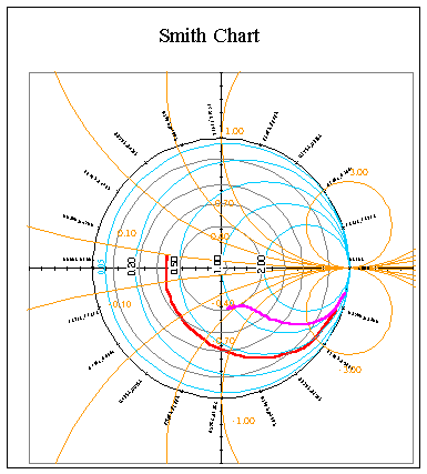
Figure 1.S11 (red) and S22 (magna) for a Silicon Germanium Transistor f = 0.045 to 40 GHz.
The Smith Chart is a mapping of the Complex Impedance of a given load to the
Reflection Coefficient of that load2. The impedance is generally normalized
to a Zo=50 ohm characteristic impedance, however other
impedances can be used.
The reflection coefficient is calculated from the load impedance as
(1)
The lower case, of course refers to the normalized impedance. The load
impedance can be expressed in terms of the reflection coefficient.
(2)
By separating the real and imaginary components of equation (2), the equations
can be rearranged to describe circles of constant resistance (r) and constant
reactance (x). The constant resistance circles are described as
(3)
Equation 3 describes a circle of constant resistance centered at
and ,
with radius .
The circles of constant reactance are described by
(4)
In this case, the circles of constant reactance are centered at
and
with radius .
To use the spreadsheet, the user simply enters the reflection coefficient data, the
values for the constant reflection coefficient circles, and the normalized values for
circles of constant resistance, and reactance.
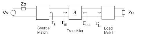
Amplifier Stability
A key parameter in amplifier design is stability3. In a microwave amplifier design,
the amplifier is typically preceded by a matching network, and followed by another
matching network as shown in figure 2. The matching networks minimize reflections,
and optimize the circuit for maximum power transfer. A properly chosen matching
network will also prevent the amplifier from oscillating. The range for choosing
allowable matching circuits is determined by calculating stability circles of the
device based on the "S" parameters for a given bias condition, and operating frequency.
Figure 2. Transistor and Typical Matching Networks
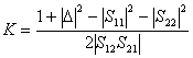
Calculation of the determinate, and the K factor of the S parameter matrix normally determine
stability. The determinate and K factor are
(5)
(6)
For unconditional stability, |D| < 1, and K > 1.
In the event these conditions are
not met, the amplifier is said to be conditionally stable and subject to oscillation.
Should potential instabilities exist the use of stability circles allow the designer
to choose matching networks, which allow the amplifier to operate in a stable state.
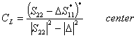
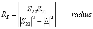
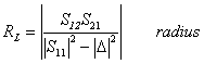
For a given set of "S" parameters the center and radius (complex
G plane) of the stability
circle for the output matching circuit is
(7)
(8)
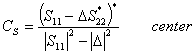
For the same S parameters, the stability circle of the input matching circuit is
(9)
(10)
Silicon Germanium Transistors
Atmel Corporation has developed a 70 GHz, ft Silicon Germanium BiCMOS process. In our
characterization of the bipolar transistors we routinely take "S" parameter data,
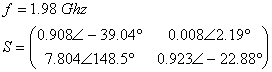
and measure device stability. As an example of a use for the Excel Smith Chart, stability
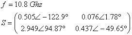
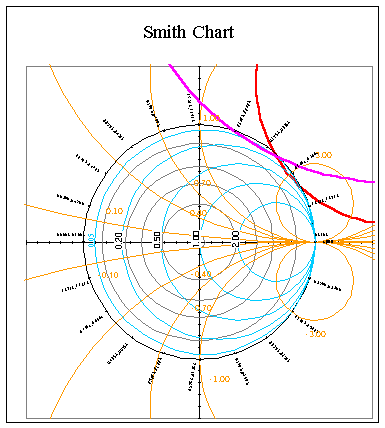
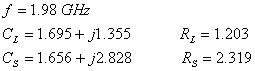
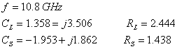
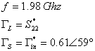
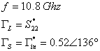
circles for frequencies of 1.98Ghz and 10.8Ghz, at a bias condition of
Vce=1.80V, and Vbe=0.86V are presented.
The transistors are in a 150mm test structure layout.
The S parameters of the device are de-embedded using standard de-embedding techniques3.
The de-embedded S parameters for the device are
(11)
(12)
Figure 3a. Stability Circles for GL (red) and
GS (magna), f = 1.98 GHz
The stability circles of the input and output matching circuits are shown in figures 3 a& b.
As both |S11| and |S22| are less than 1, the regions of stability lie in the area within the
|G| = 1 circle, and outside the stability circles.
For the f = 1.98Ghz case the transistor
is only conditionally stable as K<1. However, as the graph shows, there are only a few
matching impedances that cause oscillations.
Figure 3b. Stability Circles for GL (red) and
GS (magna), f = 10.8 GHz
(13)
(14)
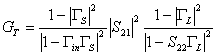
Transducer Power Gain
As a final consideration, the Transducer Power Gaini is examined. Transducer
Power Gain is defined as the ratio of power delivered to the load to the power available from the source.
4 Reference figure 2.
(15)
where
(16)
A convenient choice of matching networks, for which the transistor is stable, is
(17)
Which results in a Transducer Power Gain of
(18)
Other Applications
Many applications exist for the use of a Smith Chart. In addition to the Stability Circles,
Constant Gain Circles, and Constant Noise Figure Circles are two examples.
_____________________________________
1Philip H. Smith: A Brief Biography, Randy Rhea, Nobel Publishing, October 2000,
http://sss-mag.com/smith01.html#bio 2Field and Wave Electromagnetics, D.K. Cheng, Addison Wesley Publishing Company, 1985 3RF Measurements of Die and Packages, S.A. Wartenberg, Artech House, 2002 4 Microwave Engineering, D.M. Pozar, Addison Wesley Publishing Company, 1990
FSK Chip Developments
by Jim Pearce, Director, Pegasus
Technologies, Inc.
The need to send relatively small amounts of data over distances less than 1km
seems to be pervasive. Electric meter reading, remote control, and alarm systems
are just a few of the myriad of uses for data links that operate in the unlicensed
frequencies.
These short range transmitters are becoming common and are often paired with receivers
to make bi-directional communications systems. For many years, several integrated
circuit manufacturers have made devices that eased the RF designer's workload in
producing a data transceiver.
The first generation of devices, which came out in the late 80s - mid 90s, consisted
of little more than an amplifier stage and a mixer. All RF filters, oscillators, and
synthesizers had to be provided external to the chip. These chips were usually only
transmitters or receivers since the level of integration was too low to incorporate
a transceiver into a single chip.
The second generation of chips, from approximately 1995 - 2000, saw the introduction
of the first transceiver ICs. These usually had internal frequency synthesizers and
mixers, but often needed several special and expensive external components such as
intermediate frequency (IF) filters. Some even needed external varactor diodes for
the on-chip voltage controlled oscillator.
We are well into the 3rd generation of single chip RF transceivers. These products
are characterized by their integration of many components that used to be added
externally. IF filters have been eliminated in some cases by the use of "Zero
IF" architectures. This means that the chip converts the received signal
directly to a very low frequency, usually less than 1 MHz. At these low frequencies,
the filtering can be provided by conventional active filters that are integrated on the chip.
In this article, I will compare and make some comments on some of the recently introduced
transceiver chips. The chips that qualified for this review are all capable of operation
in the 868MHz European band and the 915MHz US band. They all use or are capable of using
Frequency Shift Keying (FSK) for their modulation, and they all had publicly available data
sheets posted on their manufacturer's web sites. I have used some, but not all, of these
chips personally in my design work with Pegasus Technologies, but
this is principally a data sheet review. Whether the chips can actually do what their data
sheets say they can do is always in question.
All of these chips are intended to be paired with some form of microcontroller which
serves as the interface to the outside digital environment.
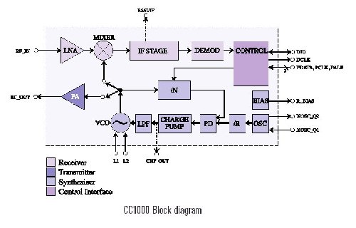
Chipcon
Chipcon is a Norwegian company that has been
producing RF ICs for many years. (Editor's Note 4/26/06: Chipcon has been acquired
by TI. Their website is still active at the present time.) Their CC1000 is a complete transceiver IC that operates
from 300 MHz to 1000 MHz. The capabilities listed in its datasheet are quite impressive.
The CC1000's frequency synthesizer, which is used for both transmit and receive modes, is
fully integrated with the small exception of a single inductor for the VCO tank. The
synthesizer covers the entire 700 MHz range of the chip in tiny 250 Hz steps.
Both the receiver and the transmitter have some very nice features:
The receiver can be programmed to use an on-chip IF filter at 150 KHz or an off-chip
10.7 MHz IF filter. Different target system requirements will point the way to which method
the designer should choose. The receiver generates a synchronized data clock from the
demodulated RF signal which greatly simplifies the firmware of the microcontroller.
The transmitter has a ramped frequency form of FSK. This method of generating
frequency shift keying relies on the synthesizer's capability of producing very small
and repeatable frequency steps. Instead of shifting, say, 60 KHz when the digital
input line shifts from a 0 to a 1, the transmitter portion of the CC1000 generates
multiple successive frequencies that sneak up on the final frequency. This greatly
reduces the bandwidth of the RF signal and makes more efficient use of the power
that is radiated.
The receive sensitivity of the CC1000 is a respectable -104 dBm for a 10-3 bit
error rate at 4.8 Kbps in the 868 MHz band. The sensitivity in the US 915 MHz band
is not listed, but is likely to be just a few dB worse than the 868 MHz spec.
The transmit power is digitally settable with a minimum of -20 dBm and a maximum
of +5 dBm in the 868 MHz band. Again, no 915 MHz spec is listed.
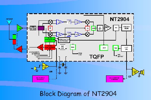
Numa NT2904
This chip is a horse of a different color! It is the only chip in this survey that
is capable of full duplex operation, i.e. it can transmit and receive simultaneously.
This is clearly targeted for use in cordless telephones. As such, the chip has
several features for FM analog operation rather than digital FSK operation.
The chip is manufactured by Numa Technologies,
a company with its headquarters in Florida that manufactures large scale ICs utilizing
BiCMOS Technology, specializing in wireless communications devices.
The Numa NT2904, which is billed as "the World's first full duplex zero-IF FM/FSK RF
transceiver IC," employs a true Zero IF receive architecture with a receive
local oscillator that operates at twice the receive frequency. This drives a
quadrature down converter which eliminates the image frequency.
The typical receive sensitivity is -94 dBm for a 10-3 bit error rate at 56.7 Kbps
and the maximum output power is 3 dBm.
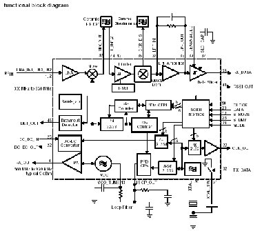
TI TRF6901
People who are familiar with the TRF6900A from Texas
Instruments might think that the TRF6901 is an incremental improvement.
In fact, it seems to be a "clean sheet of paper" design. The direct
digital synthesizer of the '6900 is gone, replaced by a simple
integer-N PLL frequency synthesizer. The two external varactors that were required
for the '6900 are gone. The VCO is completely integrated which is a welcome change.
Unfortunately, they took out digital control of the frequency shift. The shift
is now implemented by changing the load capacitance across the reference crystal
on the fly. The result of this is that a transceiver using this chip cannot have
a programmable deviation; it is set by the size of the capacitor.
Like the '6900 the '6901 uses a conventional 10.7 MHz IF and requires a ceramic IF
filter. The discriminator circuit seems to be an improvement over the one in the
'6900 and uses a standard ceramic discriminator part.
The receiver sensitivity is speced at -103 dBm for 19.2 Kbps for 860 MHz to 930 MHz.
The transmit power at the highest of its 3 power levels (well, 4 if you count zero
power) is 9 dBm.
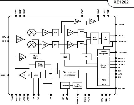
Xemics XE1202
Xemics is a Swiss fabless semiconductor company
that has made huge progress in its RF line of chips. The XE1202 has so many innovations
that it makes RF design with it almost easy! Editor's note 11/26/08: Semtech bought out Xemics.
The link above will take you to the Semtech site. They still make the XE1200 family chips.
The frequency synthesizer for this chip uses one of the latest PLL architectures, the
sigma-delta fractional N synthesizer. This allows good phase noise with small frequency
step sizes. The XE1202 has 500 Hz frequency steps in the three frequency bands that it
operates in: 433 MHz to 435 MHz, 868 MHz to 870 MHz, and 902 MHz to 928 MHz.
Like the Numa chip, the XE1202 receiver uses a Zero-IF architecture. Unlike the Numa
chip, however, it uses a local oscillator that runs at the receive frequency and generates
its quadrature signals using phase shift networks.
The XE1202 receiver has a range of features such as clock recovery and pattern matching
that make the part very friendly to the microcontroller. Its typical sensitivity is
listed as -113 dBm a 10-2 bit error rate at 4.8 Kbps. This is a very sensitive receiver
but notice that this spec is for a higher error rate than other manufacturers use to spec
their parts.
The receiver provides a digital frequency error value that lets the microcontroller implement
an automatic frequency control using no extra components. This is useful for squeezing the
last dB out of the receiver when the frequency has drifted due to temperature effects.
Although less programmable than the Chipcon part, the transmitter in the XE1202 implements
a ramped form of frequency shift keying which should have about the same net improvement
in spectral efficiency. The XE1202 transmitter has 4 programmable power levels. The
typical spec for the highest power level is +15 dBm, the highest of all chips in this review.
Final Words
My nod goes to the Xemics XE1202 as the winner in this comparison. It has the highest output power
in transmit mode and the highest receive sensitivity. The XE1202 is clearly the technical standout
in this group of chips.
The other products in this review are certainly worth consideration for projects where the mix of technical
requirements and bill-of-material cost might point in their direction.
As the market grows for wireless devices of all kinds, the IC manufacturer's will continue
to develop and expand their RF chip lineups to add more capabilities, provide lower power
options, greater flexibility, and a host of specialized ICs for different purposes.
Stay tuned -- it should be a fun ride!
This has been a busy summer for new games. We have divided our
Games Index into several categories, to make it easier for people interested in a
particular type of game (puzzle games, for example!) to find them. We've also archived
all our old games from the 1998 period -- they're still there, but in a separate section
from the new games.
the new
Most of our new games are accompanied by Game Reviews. This
is a family effort -- our chief reviewer (and player) is our almost-15 year old son, but
the rest of us get involved too. For all you gaming puzzle fans, check out my personal favorites,
Fitznik and the Penguin Puzzle -- they're both listed on the the games index and the
game review page.
Teena Rose is a certified résumé writer, interview professional, and a credentialed
career master. Select résumés have been published and featured within print publications
and are being used to set industry standards. Mrs. Rose assists job seekers regardless
of industry and magnitude of experience - even those with career blemishes.
Chances are, if you've submitted your résumé to a recruiter or a job bank, you've
been asked to convert it to ASCII format. ASCII (pronounced "as-kee") is short for
American Standard Code for Information Interchange. In short, the document is converted
to simple text so it can be read by "electronic eyes."
PURPOSE FOR THE CONVERSION
With today's technology, many recruiters, job banks, and a rising number of employers make use
of a résumé scanning system to input, track, and eventually search incoming résumés. To
read text accurately, a scanning system requires the pica and font to be clear and legible.
Recommended fonts include Courier 10 Pitch, Courier New, and Monaco because they don't utilize
long tails, slant, or dramatize the size of each letter.
GOING FROM BEAUTIFUL TO BLAND
Converting a résumé to ASCII format is a simple process, if you know what you're doing.
Steps to making your résumé ASCII friendly:
STEP 1: Highlight the entire document and change the font to one mentioned above,
along with a 10-12-font size
STEP 2: Remove hard returns, bold features, and tabs
STEP 3: Replace bullets with asterisks or dashes
STEP 4: Capitalize headers, name, and any other items that require distinction
from the remainder of text
STEP 5: Change margins: Left 1" Right 2.5"; this allows for systems accepting
only 60-70 characters per line; save file with a .txt extension
You'll know when you've achieved ASCII status - the résumé will be plain and generic in appearance.
This version should be used when requested only and not submitted in place of a Word version.