
Preview / Read the Current Issue of SSS
Volume 6 - Number 1 -- Summer 1998
August 7, 1998
[New Products -- Mitel's FH Chipset]
[The RF/SS "Handie Hopper" Transmitter]
[Interesting Wireless LAN & SS Articles]
[A Comparison Study Between TDMA and FDMA
in Digital Wireless Systems]

Part 1
SSS is proud to bring you our fifth online issue!

New Products
MITEL Semiconductor's New FH Chipset
We have seen a lot of interest in this new Frequency Hopped 2.4 GHz
Wireless Local Area Network chip set, lately. It seems to be gaining a lot of
popularity and interest with potential system integrators and Wireless Network
developers. So this product review is intended to introduce this new chip set
and set the stage for your evaluation / use of this very interesting set of devices.
First of all, MITEL is the successor to GEC Plessey's Wireless IC operations.
I'm not exactly sure when MITEL acquired these Plessey divisions, but it was
sometime in the last 18 months. The new chip set consists of three devices:
(1) WL102B -- Wireless Data Controller
(2) WL600C -- RF and IF Curcuit
(3) WL800 -- Frequency Synthesizer
These three chips represent the third generation of Plessey's DE6000 series
wireless ICs. Previous Plessey chips in this series received a lot of press, but
performed very poorly, if at all, and subsequently died natural deaths. This new
chip set is designated the DE6038 chip set by MITEL. The chip set is currently
available less than US$25 at the 1000 piece level.
The chip set is fully capable of operating an IEEE802.11 Frequency Hop network
at 1 or 2 Mb/sec data rates. A Reference Design is available, as are PCMCIA
demo cards, dubbed "WaveRider 2" boards. Limited technical information is
available on the WEB about these parts from MITEL -- what is available is at:
MITEL Wireless Data Products
We were able to find the following summary information on the individual chips from MITEL's WEB Site:
WIRELESS DATA CONTROLLER
The WL102B is a highly integrated CMOS wireless data controller designed to dramatically reduce
the cost of radio data applications. It works with the WL600C RF IF chip and WL800 synthesiser chip to offer a complete
solution for a frequency hopping, spread spectrum radio in the 2.4 to 2.45GHz ISM band.
Its flexible design means that it can also be used in a wide range of other applications using a
range of "&#micro;P" protocols and additional memory options as well as radios at other frequencies.
FEATURES
- Complete CMOS, single chip, radio transceiver controller
- Hardware implemented Commuication Control Block (CCB)
- Protocol independent design using external flash memory
- Internal 8051 and external"&#micro;P" options
- Internal/external buffer and "&#micro;P" RAM
- Block power down facility
- PCMIA/8bit "&#micro;P" host interface to buffer RAM
- Up to 1Mbps/2 level or 2 Mbps/4 level operation
2.4 - 2.5GHz RF AND IF CIRCUIT
The WL600C is a 2.4-2.5GHz RF transmitter and receiver chip for use in digital radio, and operates from a supply voltage of 2.7 - 3.6V. It is designed to work with the GPS WL800 frequency synthesiser and the WL102 WLAN controller chip which together make up the DE6038 frequency hopping Wireless Local Area Network (WLAN) transceiver.
The receiver circuit contains a low noise amplifier, image rejecting mixer, IF limiting strip with RSSI and a quadrature demodulator. There is also a power amplifier driver stage and ramp control facility for use in transmit.
FEATURES
- Part of DE6038 chipset (WL800, WL102)
- High level of integration
- Low noise figure
- Low power consumption
- High data rates with comparator for 2 level FSK
- Minimal external components
- 48 lead LQFP package
2.5GHz Frequency SynthesiserPreliminary Information
The WL800 is a low power single chip frequency synthesiser. The circuit is fabricated on Mitel Semiconductor HG process and operates from a supply voltage of 2.7 - 3.6V. It is designed to work with the Mitel Semiconductor WL600C RF and IF circuit and the WL102 WLAN controller chip which together make up the DE6038 frequency hopping Wireless Local Area Network (WLAN) transceiver.
FEATURES
- Low power consumption
- 2.5GHz input
- Forms complete phase locked loop using external VCO and loop components
- Serially programmed via 3 wire bus
- Contains anti-modulation circuit
- Part of DE6038 Chip-set (WL600C, WL102)
Sounds interesting so far, doesn't it? Well MITEL is making a big marketing
pitch on this chip set and visiting many potential system integrators. They
are demonstrating their WaveRider 2 PCMCIA boards and giving away the
reference design kit, complete with PCB artwork, Bill of Materials (BOM) and
schematics. The documentation they are furnishing is rather incomplete
and the development kit has very limited test capabilities in hardware or
software. One final criticism, take a very close look at their BOM and
schematic, it seems that some of the parts called for are almost "pure
un-obtainium!"
In conclusion, I like what MITEL has done so far! They have some good
ideas, good parts and are aggressively marketing their stuff. But, if you
have ever heard me spout off about Plessey -- some of the same can be
said for MITEL! Plessey was notorious for obsoleting parts without ever
giving their customers advance notice. Plessey rarely had second sources
for their parts. Finally, Plessey virtually thought customers were a bother!
I sincerely hope that MITEL can improve on Plessey's past track record
and consistantly deliver good products and great customer support. MITEL
is certainly making waves with this new technology -- can they really deliver
what this Wireless market place needs and wants?
If your company has a new chip or chipset product that we have missed or that
you feel should be included here, please email us with some more information.
The RF/SS "Handie Hopper" 1/4 Watt
915 MHz FH Transmitter
Over the last few years we have had numerous inquiries about simple and inexpensive
frequency hoppers for the 915 MHz ISM (the license-free US Industirial, Scientific and
Medical frequency range -- also known as FCC Part 15) band. Most people seem to
want a low data rate, slow hopping unit that is "dirt cheap" to produce. Normally I have
shunned these requirements, since my interest is normally on the higher end, higher
performance systems. But, it seems that technology has advanced again without any
of us really noticing it! A number of new chips and techniques make a 0.25 Watt, US$20
FH transmitter and a perhaps US$35 receiver practical, today.
This article will introduce a transmitter design that we recently completed in breadboard form.
This section of the article covers the transmitter, while a forthcoming article on the receiver
will be presented in Part 2 of this issue of SSS Online. The very simple FH transmitter we have
christened the "Handie Hopper" since it is a highly capable, easily producible, low cost,
general purpose design. Applications for this radio include security systems, low speed
telemetry systems, various monitoring and control systems, very low speed "event"
recording systems and long range, very sensitive, low data rate communications of all sorts.
I have had potential clients want variants on this design but I always dicouraged them from
an approach like this. Now, however, I feel that the requisite technologies have matured and
low cost, simple, FH data links are extremely viable. For more details on this new design --
please read on!
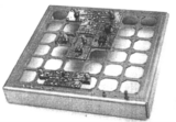
A photo of the transmitter breadboard appears below. This breadboard was built with
"ProtoCell*" breadboard PCB modules in a 8.26 cm x 8.26 cm x 2.54 cm (3.25" x 3.25" x
1" high) aluminum enclosure. "ProtoCells" are one inch (2.54 cm) square pre-etched
PCBs that allow rapid and accurate breadboarding of RF circuits. More about ProtoCells
later, but let me point out that this entire transmitter was breadboarded, assembled and
tested in under 8 hours total, thanks to the Protocell approach. Sure, I spent another
4 or 5 hours "optimising" various circuits and component values -- but the actual time
to the first "smoke" test was just 8 hours!
Circuit side view of Handie Hopper Transmitter in 3 x 3 CellPax enclosure.
To highlight some of this unit's capabilities, its basic specifications and capabilities are listed below:
- 902 to 928 MHz, FCC Part 15.247 Frequency Hop Operation
- Hop Channel steps from 125 to 500 kHz
- Frequency Hop rate up to at least 40 hops per second
- PLL sythesizer switching times of 1 to 2.5 milliseconds
- Modulation MSK / FSK
- Data rates 600 bps to 38.4 kbps
- RF Power output nominal 0.3 Watt / 0.25 Watt minimum
- Spurious outputs below -55 dBc
- Harmonics below -40 dBc
- Occupied bandwidth 50 kHz at -20 dB and 38.4 kbps MSK
- Uses on-board 50 ppm, 24 MHz TCVCXO oscillator
- 5 VDC primary power input (usable down to 3VDC)
- Current drain 0.3 Amps at 5VDC
- Simple data and control interface to RS-485 or RS-232
- 3 wire PLL frequency control interface
- Easily interfaces to PIC microprocessors such as 16F84 or Parallax Basic Stamp
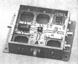
The current schematic of the Handie Hopper is shown below. Note that there really is
nothing "earthshaking" or really new in this design. Rather it is an interesting
combination of new chips, standard circuit techniques and a few "tricks." The design
is based on readily available parts and starts off with a packaged Mitsubishi 900 to
960 MHz, 5VDC VCO with a power output of about -3 dBm. A MAR-6 buffers the VCO
output and brings up to the power level of a few milliwatts. The Power Amplifier stage is
an RF2103P from RF Microdevices. The power amp is followed by a simple tee section
low pass filter to eliminate harmonics.
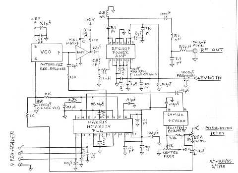
Schematic of basic Handie Hopper Transmitter.
 CLICK HERE to Download a full sized (8" x 10") CLICK HERE to Download a full sized (8" x 10")
schematic in .pdf format -- (1.1M)
The real heart of this design is the use of the Harris HFA3524 dual PLL IC. In the high
current phase detector mode, this design can switch frequencies in under 1 millisecond
(under 2.5 milliseconds at 1 milliamp). This is with a loop bandwidth of about 1 kHz and
a channel spacing of 250 kHz. By the way, channel spacing and (of course , actual hop
frequencies) are fully programmable with this chip. Finally the frequency reference for
the PLL comes from an Ecliptek 24 MHz TCVCXO which is capable of swinging
+ / - 100 ppm.
One of the "tricks" in this design is how the unit is FM modulated. Note that at frequencies
above the PLL's loop bandwidth, the modulation is AC coupled into the transmitter's VCO
directly. However, at modulation frequencies within the PLL loop bandwidth, we modulate
(with DC coupling) the TCVXO at 24 MHz. The PLL tracks this modulation and acts as a
sort of high order frequency multiplier in this mode. No cross over or high pass - low filter
network is necessary in this application, since the PLL performs this cross over function
on the modulation automatically. Seperate adjustments for deviation sensitivity of each
VCO are required to make this "trick" work properly, but this is a small price to pay for
modulation frequency response essentially all the way down to DC! In our tests, low
frequency "droop" of the received data stream was less than 10% for modulation rates
from 600 bps to 38.4 kbps even with a 20 bit (1 million bits) long pseudo random data
stream. The MItsubishi VCO we used here was internally rolled off with a 1000 pf capacitor
at its modulation input. So its modulation frequency response was rather limited. Our
transmit and receive tests showed a receive eye pattern that had about 15% closure at a
data rate of 38.4 kbps. Other wider band VCOs should be capable of achieving a
significantly higher end on the modulation data rate. One of our goals here was to use as
small a receive bandwidth (for the highest receive sensitivity possible) consistant with
inexpensive oscillators and low cost 10.7 MHz ceramic IF filters. Thus we choose to use
a deviation of 38.4 kHz at all data rates (which gives MSK-like modulation at 38.4 kbps)
and allows the use of IF ceramic filters that are 115 kHz wide. Thus a total frequency error
budget of about 75 khz is availble for transmitter and receiver frequency inaccuracies. If
more money can be spent on the receiver, then a transmitter drift of 50 ppm allows the
receiver to use 25 ppm oscillators. But perhaps a better solution is use AFC control on the
receiver and allocate essentailly all of the "drift" budget to the transmitter. I leave these
detailed trade-offs up to you to solve, in the most optimum way that your application
demands.
Other details of this design are also left to user / designer choices. For instance the
details of supplying the three-wire serial PLL frequency commands (for implementing
Frequency Hopping), Host interface and RTS/CTS handshaking, transmitter power
on / off ramping, transmitter power control, etc. are all available for customization and implemenatation
details certainly depend on the requirements of the particlar application. My personal
approach is to add a Microchip PIC 16F84 (or a Basic Stamp) to the transmitter to
accomplish the required data I/O and transmitter control functions. The use of a PIC
in this application is attractive since the PIC processor contains RAM, ROM and rest
circuitry and only needs an outboard clock oscillator crystal to function as a standalone
controller. The PIC can also be added to this basic transmitter design for US$2 to US$8,
depending on exactly which PIC is chosen. Anyone who starts to use this basic design
should carefully analyze his / her requirements before committing to a complete interface
design. One possible and interesting implementation might use a small to medium sized
XILINX or other FPGA to accomplish all I/O and control with dedicated logic instead of
a microprocessor. Use your imagination and creativity here and enjoy entering the
world of Frequency Hopped Spread Spectrum Wireless.
Of course the real test of a good transmitter design is how well it does with a companion
reciever. The matching receiver will be presented in Part 2 of this issue very soon. For
now, we hope you can use some of the ideas presented here in our "Handie Hopper" in
your next FH project.
* Innovative Technology's "ProtoCell"
System
Innovative Technology's "ProtoCell" System Provides the
RECIPE for Rapid Prototyping:
Begin with parts . . .
Attach to ProtoCell Boards . . .
Combine with ProtoFrame
or CellPax Enclosures
And Get Prototype Circuits Running Quickly!
For more information, contact:
Innovative Technology
2027 W. 233rd Street
Torrance, CA 90501
TEL/FAX: 310-325-7976
Interesting Wireless LAN & SS Articles
We've come across a number of very interesting and useful articles
relating to some of our favorite subjects, recently on the WEB. The
following links will take you to the best of the current crop. Take a look!
[Editor's Note 2/2/09: broken links have been repaired if possible, or deactivated.]
 "Wireless Design Online" (Sort of a Competitor) "Wireless Design Online" (Sort of a Competitor)
"(MITEL) Chip Set Targets FHSS WLAN Applications," from Wireless Design Online
"Bluetooth Technology", from Intel
Andrew Seybold's
"The Convergence of Communications and Computing" 
The Pacific Group's "Tech-Brief...Bluetooth"
"Win-Win Scenario for ... Amateur Radio and Part 15.247 Suppliers"
A Comparison Study Between TDMA and FDMA
in Digital Wireless Systems
By Kizito Tshilumba Kasengulu
Berocom Inc., Montreal, Canada
ABSTRACT: This paper explains the differences between TDMA and FDMA in digital cellular systems.
For the case of TDMA, I give a general expression for the frame efficiency and the number of speech
channels per frame. For both systems, I concentrate my study on the spectral efficiency and system
capacity. I give the parameters which influence them and their nature. I have also done a
qualitative comparison between the two multiple access technologies and have explained why TDMA
is so poular today.
Download the full article in .pdf format --
(382K)
In October 2000, this website and the copyright to all editions of
Spread Spectrum Scene Online was purchased by
SSS Online, Inc., and is operated by
Pegasus Technologies. For more of the best information
on RF, Spread Spectrum and wireless, press one of the buttons below:

|
|
|